
Increasing output is valuable only when film quality and production stability remain under control. For LLDPE blown-film manufacturers, sharkskin, persistent die-lip deposits, and frequent cleaning can limit the productivity gained from higher extrusion rates.
To reduce die build-up and melt fracture, first distinguish the defects, then review resin rheology, die condition, melt temperature, formulation, and throughput. A suitably selected polymer processing aid may help when melt-flow instability or polymer–metal interactions contribute to the problem, but it cannot replace equipment maintenance or correct thermal degradation.
This guide explains how to identify the likely causes, compare corrective approaches, and evaluate PFAS-free PPA solutions under production-relevant conditions.
Why Can Higher Extrusion Output Increase Processing Problems?
With resin, die geometry, and melt temperature held broadly constant, increasing extrusion output generally increases flow velocity and deformation rates through the die. This can raise flow stresses and move the melt beyond its stable processing window.
However, extrusion output and haul-off speed are not interchangeable.
Increasing haul-off speed at constant extrusion output primarily changes film drawdown and thickness; it does not necessarily increase flow through the die. Troubleshooting should therefore record output in kg/h separately from haul-off speed in m/min.
Higher output may intensify existing flow or deposit problems, but melt fracture and die build-up should not be treated as successive stages of the same failure.
Melt Fracture and Die Build-Up: What Is the Difference?
Sharkskin: Fine Surface Distortion
Sharkskin commonly appears as fine, repetitive roughness on the extrudate surface. It is associated with rapid deformation and tensile stresses near the die exit as the surface layer accelerates from the constrained flow inside the die into the emerging extrudate.
Its onset depends on resin rheology, temperature, die geometry, and boundary conditions.
Gross Melt Fracture: More Severe Flow Instability
Gross melt fracture involves larger-scale extrudate distortion and may arise from instabilities within the die or its entrance region.
It is not simply an inevitable later stage of sharkskin. The dominant mechanism and effective corrective action may differ.
Die Build-Up: Material Accumulation at the Die Lip
Die build-up, often called die drool, is material accumulation near the die exit. Possible contributors include formulation components, degradation products, local flow conditions, and die-surface condition.
Deposits may discolor, grow, or detach into the film. They can occur with or without visible melt fracture.
The practical implication: a smoother film surface does not, by itself, prove that die build-up has been resolved. Monitor both separately.
What Should an Extrusion Team Check First?
1. Resin Rheology and Blend Composition
LLDPE grade, melt index, molecular-weight distribution, comonomer type, and blend composition influence the processing window.
Changes in LDPE content, mLLDPE grade, recycled material, or supplier can alter flow behavior even when the nominal melt index appears similar. Melt index alone does not fully describe high-shear extrusion performance.
Compare the current formulation with the last stable production run before selecting an additive solution.
2. Die Condition and Flow Restrictions
Inspect die lips, die-gap uniformity, flow surfaces, screens, and filtration components.
Contamination, damaged surfaces, deposits, or increasing screen resistance may create localized stress or unstable pressure. Record where pressure is measured: a rise upstream of a blocked screen is not the same as a change in pressure associated with the die.
A PPA will not repair a damaged die or remove the cause of persistent contamination.
3. Actual Melt Temperature and Thermal History
A controlled increase in melt temperature may lower viscosity and delay some surface instabilities. However, higher temperature can also increase degradation risk or alter bubble cooling and stability.
Check actual melt temperature where measurement is available, rather than relying only on barrel setpoints. Review residence time, stagnant regions and shutdown history when discoloration or deposits suggest thermal degradation.
4. Additives and Their Interactions
Slip agents, antiblock particles, pigments, fillers, and other ingredients can influence dispersion, flow, surface behavior, or PPA response.
Evaluate the processing aid in the intended production formulation. Results in neat resin may not transfer directly to a pigmented, recycled-content or multilayer film.
5. Output and Operating Conditions
Record extrusion output, screw speed, die gap, die diameter, melt temperature, pressure, layer ratios, and film thickness.
For multilayer lines, record output and additive dosage by extruder. These details help distinguish a formulation problem from a change in flow distribution or operating conditions.
Common Approaches to Reducing Melt Fracture and Die Build-Up
|
Approach |
Where it may help |
Important limitation |
| Adjust melt temperature | May reduce viscosity and delay some flow instabilities | Excess heat can increase degradation and affect cooling |
| Reduce extrusion output | Can lower flow stress and help identify a throughput-related limit | Reduces productivity and may not address the underlying cause |
| Change resin or blend ratio | May widen the stable processing window | Can affect mechanics, sealing, optics and cost |
| Clean or service the die and filtration system | Addresses contamination, deposits and equipment-related restrictions | Deposits may recur if formulation or thermal causes remain |
| Review the additive package | Can identify incompatible, poorly dispersed, or deposit-forming components | Changes require validation of final-film properties |
| Evaluate a polymer processing aid | May help control melt fracture and certain die-build-up problems | Requires suitable chemistry, dosage, and trial conditions |
Choose the corrective action according to the observed defect. Increasing PPA dosage is not a reliable response to every pressure increase or die deposit.
How Can a PFAS-Free PPA Support Blown-Film Extrusion?
Depending on its chemistry, a PFAS-free polymer processing aid can influence polymer–metal interactions and melt-flow behavior.
In a suitable formulation, this may help:
• Clear existing melt fracture or delay its onset as output increases.
• Reduce die pressure under controlled comparison conditions.
• Limit certain types of die-lip accumulation.
• Support a wider stable extrusion window.
These outcomes are not automatic or identical across PFAS-free technologies.
Some systems require a conditioning period before a stable response develops. Resin composition, previous PPA use, dosage, die history and processing conditions can influence the time required.
A meaningful evaluation should distinguish initial conditioning behavior from steady-state performance.
A Practical PFAS-Free PPA Transition and Trial Procedure
Step 1: Establish a Measurable Baseline
Record the resin blend, layer structure, current PPA grade, dosage by layer, output, melt temperature, pressure, and film thickness.
Document melt fracture using a consistent inspection method. Record die-lip deposits separately, including their location, appearance, and time since the last cleaning.
Step 2: Agree on the Transition Procedure
Residual fluoropolymer PPA or another processing aid may influence early trial results.
Review carryover from the extruder, die, feeders, and reclaim streams. Use a supplier-agreed transition or purging procedure appropriate for the equipment and formulation.
Do not assume that a visually clean film immediately after switching demonstrates the new PPA’s independent performance.
Step 3: Introduce the Recommended Trial Dosage
Use the product-specific evaluation level agreed with the technical team.
Some procedures may use a higher initial conditioning level followed by a lower steady-state dosage. Such procedures should be treated as formulation-specific recommendations, not universal recipes.
In coextrusion, state whether dosage refers to an individual layer or the total film.
Step 4: Maintain a Controlled Operating Point
Hold output, temperature, and other relevant variables as steadily as practical while the response develops.
If changes are necessary for safety or product quality, record them. Avoid adjusting several settings simultaneously, as this makes the result difficult to interpret.
Step 5: Measure the Response Over Time
Track:
• Time to partial and complete melt-fracture clearing.
• Pressure at a consistent measurement location.
• Torque or motor load.
• Die-lip accumulation over a defined running period.
• Film appearance, gauge consistency and bubble stability.
A short run may reveal melt-fracture response but may not be long enough to establish a reliable cleaning interval.
Step 6: Validate Film Quality and Conversion
Check haze, gels, sealing and the downstream processes relevant to the application, including printing and lamination.
Processing improvement alone is insufficient if the film no longer meets its conversion or end-use requirements.
Step 7: Optimize Dosage and Output Separately
After stabilization, optimize dosage in controlled steps. Evaluate higher output separately so that the effect of each change remains clear.
If energy savings are an objective, measure energy per unit of acceptable output, such as kWh/kg, over a defined equipment boundary. Lower torque or current alone does not establish lower specific energy consumption.
Selecting a SILIMER PFAS-Free PPA for PE Blown Film
SILIKE develops SILIMER PFAS-free PPA solutions for PE film extrusion.
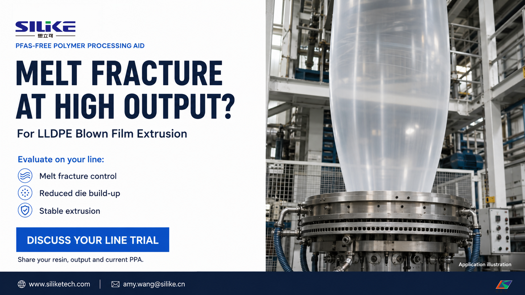
SILIMER 9301 PFAS-free PPA masterbatch can be evaluated as a ready-to-use option for PE blown-film processing.
Where the resin blend or operating conditions require a different solution, SILIKE’s technical team may recommend another grade, such as fluorine-free processing additive masterbatch SILIMER 9401A, after reviewing the application.
Selection should consider:
• Resin grades and blend ratios.
• Existing processing aid and dosage.
• Film layer structure and additive allocation.
• Output target and operating conditions.
• Melt-fracture and die-build-up behavior.
• Printing, lamination, and sealing requirements.
Explore SILIKE PFAS-free PPA masterbatches to discuss options for your formulation.
The most useful comparison is a controlled trial against the current formulation, using consistent operating conditions and acceptance criteria.
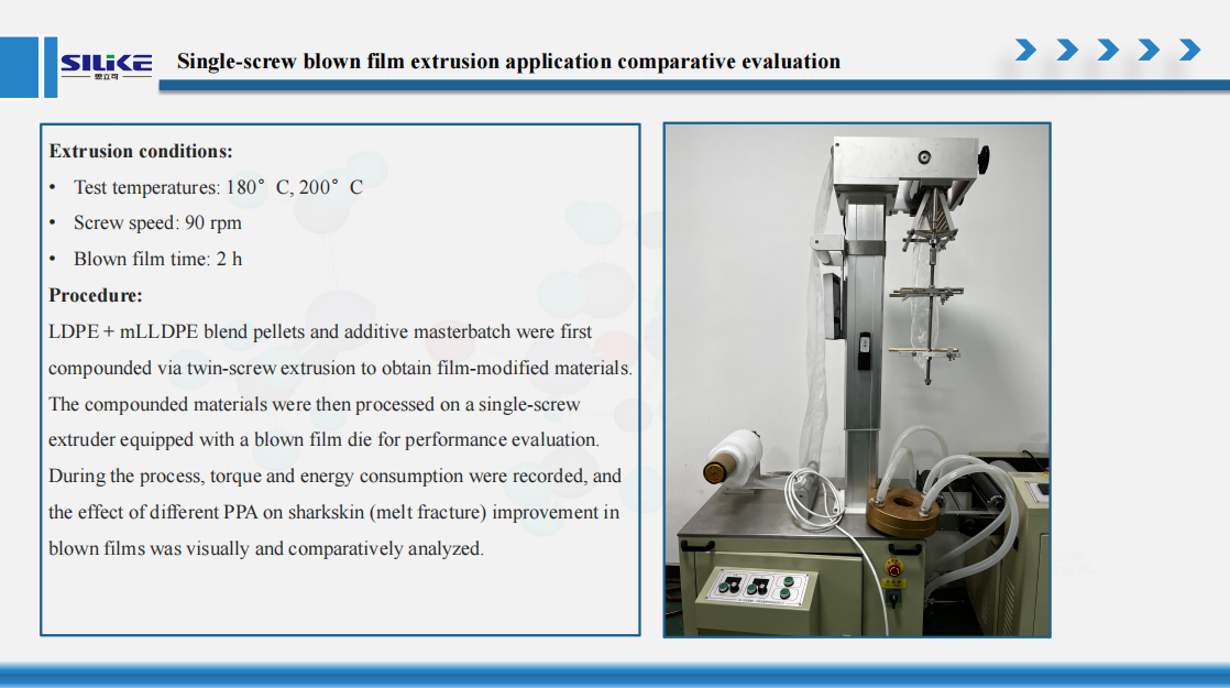
SILIKE Internal Test Data: SILIMER PFAS-Free PPAs for Blown Film Extrusion
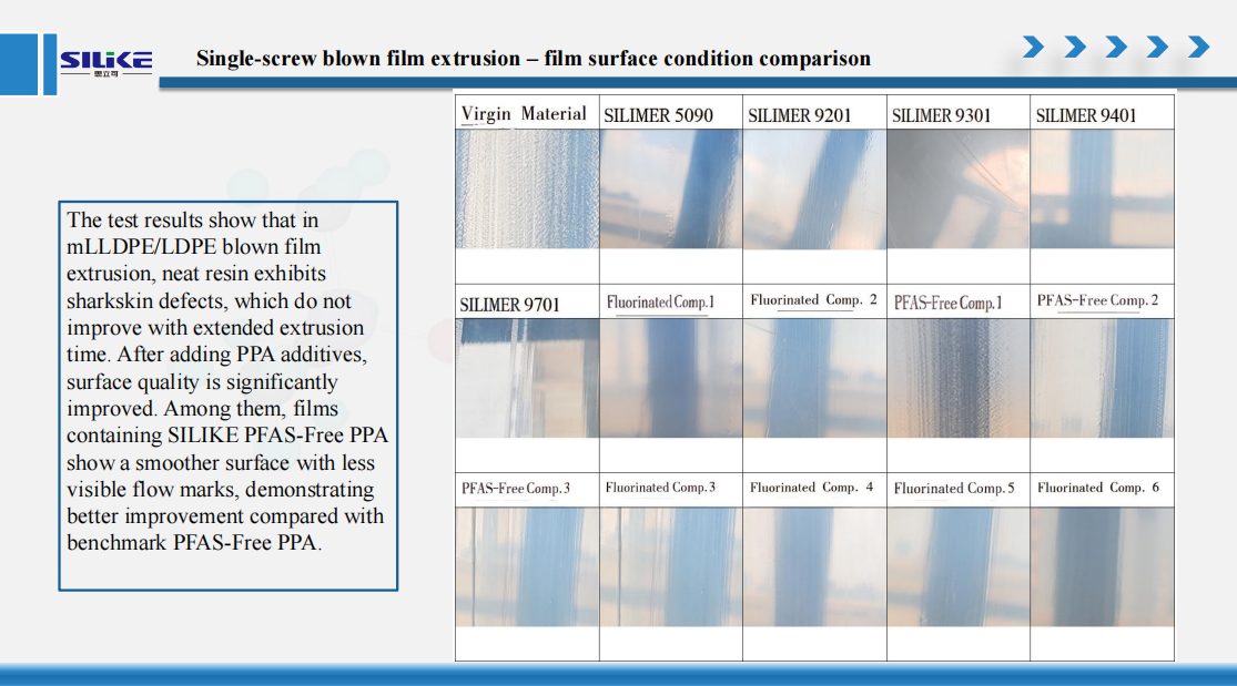
PFAS-free PPA comparative evaluation in LDPE and mLLDPE blown film extrusion for melt fracture reduction, torque, and energy consumption.
Insight:
SILIKE SILIMER series PFAS-free PPAs not only reduce die build-up (die drool) and address melt fracture (sharkskin) performance but also enhance overall processing efficiency.
Note: The results shown above are selected findings from SILIKE’s internal blown-film extrusion evaluations. Performance depends on the formulation and processing conditions. For complete test data, detailed test conditions, and guidance on selecting a suitable SILIMER PFAS-free PPA for your application, please contact SILIKE’s technical team.
Frequently Asked Questions
Can increasing extrusion temperature eliminate sharkskin?
It may lower viscosity and delay or reduce sharkskin under some conditions. However, temperature adjustment has limits and may introduce degradation or cooling problems. Review resin, die geometry and output alongside temperature.
Does higher haul-off speed cause melt fracture?
Not necessarily. At constant extrusion output, higher haul-off speed mainly changes drawdown and thickness. Melt-fracture risk is more directly related to melt flow through the die and the associated deformation stresses.
Are die build-up and melt fracture the same problem?
No. Melt fracture is a flow instability; die build-up is material accumulation at the die lip. They may occur together, but each requires its own diagnosis and performance check.
Should output be reduced when starting a PFAS-free PPA trial?
Not automatically. A controlled operating point helps evaluate conditioning behavior. Output reduction may be appropriate if the line is outside a safe or usable operating window, but it should be documented as a separate trial variable.
How long does PPA conditioning take?
There is no universal time. Product chemistry, dosage, resin, equipment history, and operating conditions all matter. Record the response over time and use a supplier-agreed evaluation window.
Can one PPA grade work in every PE formulation?
Performance can vary across LDPE, LLDPE and mLLDPE blends, additive packages and multilayer structures. Select the grade for the actual application and confirm it through testing.
Conclusion
Reducing die build-up and melt fracture in LLDPE blown-film extrusion starts with identifying the defect and its likely cause.
Higher output can increase flow stresses, but die deposits may also involve degradation, formulation components or equipment condition. A PFAS-free PPA can be a useful part of the solution when selected and evaluated within that wider process context.
The goal is not simply a lower pressure reading or a temporarily smoother film. It is a repeatable operating window that combines acceptable film quality, manageable deposits and reliable downstream conversion.
Discuss a PFAS-Free PPA Trial for Your LLDPE Blown-Film Line
Are melt fracture or die-lip deposits limiting your production output?
Share your resin grades, blend and layer structure, current PPA and dosage, extrusion output, temperature profile, pressure readings and defect observations. Include your printing, lamination or sealing requirements.
SILIKE’s application team can help identify a suitable SILIMER PFAS-free PPA and recommend a controlled trial procedure for your line.
Website: www.siliketech.com
Email: amy.wang@silike.cn
Mobile / WhatsApp: +86-15108280799
Post time: Sep-04-2026


